
The TCP/IP model vs. the OSI model
The TCP/IP model is a framework used to visualize how data is organized and transmitted across a network. This model helps network engineers and security analysts conceptualize processes on the network and communicate where disruptions or security threats occur.
The TCP/IP model has four layers: the network access layer, internet layer, transport layer, and application layer. When analyzing network events, security professionals can determine what layer or layers an attack occurred in based on what processes were involved in the incident.
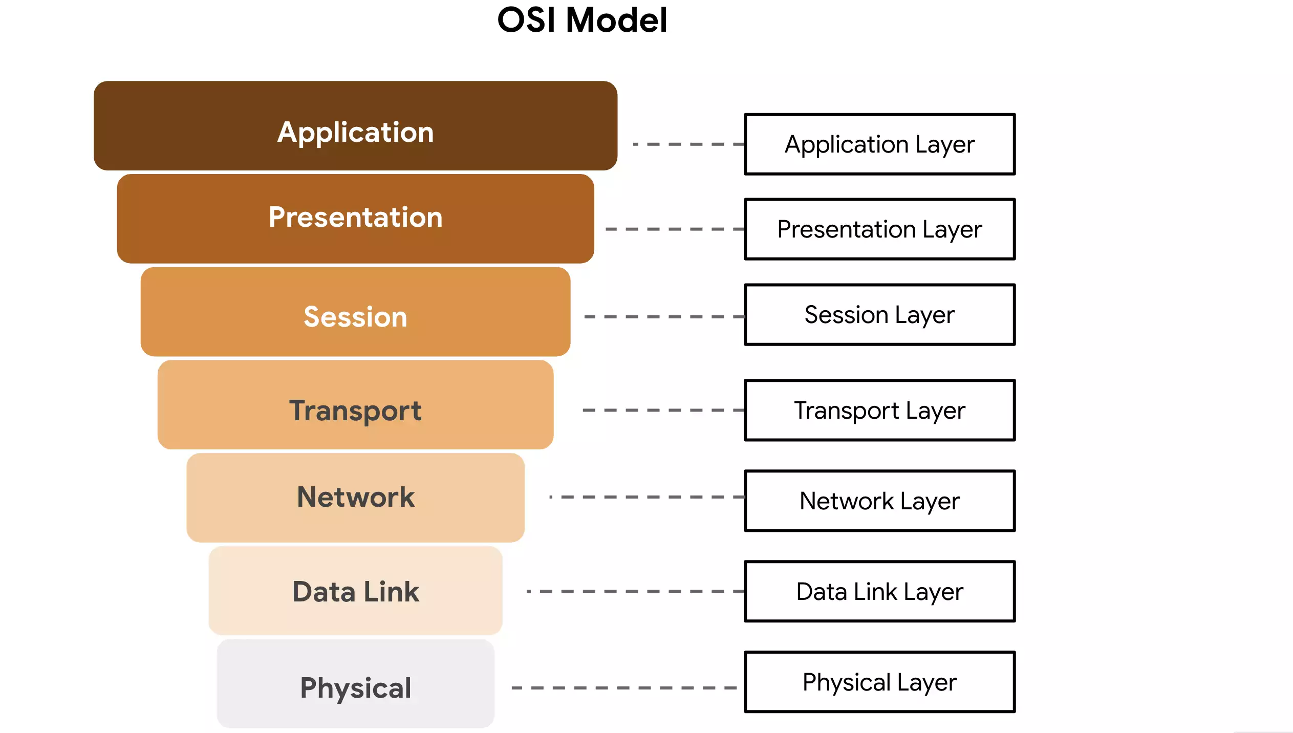
The OSI model is a standardized concept that describes the seven layers computers use to communicate and send data over the network. Network and security professionals often use this model to communicate with each other about potential sources of problems or security threats when they occur.

Some organizations rely heavily on the TCP/IP model, while others prefer to use the OSI model. As a security analyst, it’s important to be familiar with both models. Both the TCP/IP and OSI models are useful for understanding how networks work.
Layer 7: Application layer
The application layer includes processes that directly involve the everyday user. This layer includes all of the networking protocols that software applications use to connect a user to the internet. This characteristic is the identifying feature of the application layer—user connection to the internet via applications and requests.
An example of a type of communication that happens at the application layer is using a web browser. The internet browser uses HTTP or HTTPS to send and receive information from the website server. The email application uses simple mail transfer protocol (SMTP) to send and receive email information. Also, web browsers use the domain name system (DNS) protocol to translate website domain names into IP addresses which identify the web server that hosts the information for the website.
Layer 6: Presentation layer
Functions at the presentation layer involve data translation and encryption for the network. This layer adds to and replaces data with formats that can be understood by applications (layer 7) on both sending and receiving systems. Formats at the user end may be different from those of the receiving system. Processes at the presentation layer require the use of a standardized format.
Some formatting functions that occur at layer 6 include encryption, compression, and confirmation that the character code set can be interpreted on the receiving system. One example of encryption that takes place at this layer is SSL, which encrypts data between web servers and browsers as part of websites with HTTPS.
Layer 5: Session layer
A session describes when a connection is established between two devices. An open session allows the devices to communicate with each other. Session layer protocols keep the session open while data is being transferred and terminate the session once the transmission is complete.
The session layer is also responsible for activities such as authentication, reconnection, and setting checkpoints during a data transfer. If a session is interrupted, checkpoints ensure that the transmission picks up at the last session checkpoint when the connection resumes. Sessions include a request and response between applications. Functions in the session layer respond to requests for service from processes in the presentation layer (layer 6) and send requests for services to the transport layer (layer 4).
Layer 4: Transport layer
The transport layer is responsible for delivering data between devices. This layer also handles the speed of data transfer, flow of the transfer, and breaking data down into smaller segments to make them easier to transport. Segmentation is the process of dividing up a large data transmission into smaller pieces that can be processed by the receiving system. These segments need to be reassembled at their destination so they can be processed at the session layer (layer 5). The speed and rate of the transmission also has to match the connection speed of the destination system. TCP and UDP are transport layer protocols.
Layer 3: Network layer
The network layer oversees receiving the frames from the data link layer (layer 2) and delivers them to the intended destination. The intended destination can be found based on the address that resides in the frame of the data packets. Data packets allow communication between two networks. These packets include IP addresses that tell routers where to send them. They are routed from the sending network to the receiving network.
Layer 2: Data link layer
The data link layer organizes sending and receiving data packets within a single network. The data link layer is home to switches on the local network and network interface cards on local devices.
Protocols like network control protocol (NCP), high-level data link control (HDLC), and synchronous data link control protocol (SDLC) are used at the data link layer.
Layer 1: Physical layer
As the name suggests, the physical layer corresponds to the physical hardware involved in network transmission. Hubs, modems, and the cables and wiring that connect them are all considered part of the physical layer. To travel across an ethernet or coaxial cable, a data packet needs to be translated into a stream of 0s and 1s. The stream of 0s and 1s are sent across the physical wiring and cables, received, and then passed on to higher levels of the OSI model.